You can run an electronic switch command on the SCUB control board to set the GE port on the board to an uplink port. The uplink port on the upstream interface board like GICF/X2CS and the uplink port on the control board cannot be used for upstream transmission at the same time. You can use only either of them at a time.
Can the Huawei S2700/S3700/S5700/S6700 Switches Use AC and DC Power Supply Simultaneously?
In versions prior to V100R006C01, the S2700, S3700, and S5700 cannot use AC and DC power supply simultaneously.
In V100R006C01 and later versions, the S3700-26C-HI, S5700-28C-HI, and S5700-28C-HI-24S can use AC and DC power supply simultaneously. S6700 cannot use AC and DC power supply simultaneously.
In V200R001C00 and later versions, the S5710-28C-EI and S5710-52C-EI can use AC and DC power supply simultaneously.
In versions prior to V200R005C00, the S6700-EI cannot use AC and DC power supply simultaneously.
In V200R005C00, the S5700-EI (non-PoE), S5700-SI (non-PoE), and S6700-EI can use AC and DC power supply simultaneously.
In V200R006C00 and later versions, the S5720-HI (non-PoE) can use AC and DC power supply simultaneously.
The S5720-C-EI (non-PoE) and S5720-PC-EI (non-PoE) can use AC and DC power supply simultaneously.
The S5720-SI (non-PoE), S6720-EI, and S6720S-EI can use AC and DC power supply simultaneously.
GPON ONU Profile Match state is Mismatch
An ONU connected to a GPON port of an Huawei OLT can go online successfully, but the queried Match state of the ONU is displayed as mismatch by running the display ont info command on the OLT.
Context
The ONU matching status indicates whether the actual ONU capability is the same as the service profile bound to the ONU. The status includes: initial, mismatch, and match. To some extent, the matching status is determined by the ONU running status and configuration status.
- The matching status of the ONU can be queried only when the ONU running status is online. The matching status is match when the actual hardware capability of ONU is the same as the ONU service profile bound with the ONU. Otherwise, the status is mismatch.
- In other configuration states, the matching status is initial.
- The ONU matching status does not affect the normal forwarding of the service flow, and only indicates whether the actual ONU capability is the same as the service profile bound to the ONU.
In practice, ONUs in the offline state are bulk pre-configured on the OLT to facilitate service provisioning. An ONU service profile and an ONU line profile are specified during such configurations. The ONU profiles together can be regarded as a virtual ONU. Subsequent services are configured based on this virtual ONU. Inconsistency between the capability set configured in the ONU profiles and the actual ONU capabilities involves the following two situations:
- The configured capability set outmatches the actual ONU capabilities. If the ONU is bound to such ONU profiles, ONU configurations will fail to match when the ONU goes online.
- The configured capability set undermatches the actual ONU capabilities. In this case, the ONU capabilities that are not covered by the ONU profiles will fail to be configured or applied.
Location Method
When the queried Match state of the ONU is displayed as mismatch, locate the fault according to the following procedure:
- Check whether the capability set configured in the ONU service profile matches the actual ONU capabilities.
-
Procedure
- Run the display ont capability command to query the actual ONU capabilities. According to the data plan, modify the current ONU profiles, or bind matching ONU profiles to the ONU.
- If this problem occurs on all the ONUs of the same type, the configurations of the ONU profiles may be incorrect.
- If the OLT works in the distributed mode, the profiles that are bound to the ONU cannot be modified or deleted. In this case, bind matching ONU profiles to the ONU.
- If the OLT works in the profile mode:
- Run the display ont-srvprofile command to query the information about the ONU service profile and run the display ont-lineprofile command to query the information about the ONU line profile.
- Modify the ONU profiles by referring to Configuring a GPON ONT Profile in the Commissioning and Configuration Guide.
- If this problem occurs on only one ONU, it is suggested to bind matching ONU profiles to the ONU.
- If the OLT works in the distributed mode:
- Run the display ont-profile command to query the current ONU profiles that are configured on the OLT.
- If the OLT does not have matching ONU profiles, run the ont-profile add command to add matching ONU profiles.
- Run the ont modify command to bind the ONU profiles to the ONU.
- If the OLT works in the profile mode:
- Run the display ont-srvprofile command to query the information about the ONU service profile and run the display ont-lineprofile command to query the information about the ONU line profile.
- If the OLT does not have matching ONU profiles, add matching ONU profiles by referring to Configuring a GPON ONT Profile in the Commissioning and Configuration Guide.
- In the GPON mode of the OLT, run the ont modify command to bind the ONU profiles to the ONU.
- If the OLT works in the distributed mode:
- If this problem occurs on all the ONUs of the same type, the configurations of the ONU profiles may be incorrect.
- Check whether Match state of the ONU is displayed as match.
- Connect Huawei for technical support.
- The fault is rectified.
- Run the display ont capability command to query the actual ONU capabilities. According to the data plan, modify the current ONU profiles, or bind matching ONU profiles to the ONU.
There is many error message on optical modules saying that the power is too low in Huawei S6700 Switch
Issue Description
There is many error message on optical modules saying that the power is too low in Huawei S6700 Switch
Alarm Information
May 23 2014 15:36:09+01:00 FEDERATEUR-RG %%01SRM/3/RXPOWER_EXCEEDMINOR(l)[25]:Optical module in interface XGigabitEthernet0/0/7 exception, Rx power is too low.
May 23 2014 15:34:48+01:00 FEDERATEUR-RG %%01SRM/3/RXPOWER_EXCEEDMINOR(l)[26]:Optical module in interface XGigabitEthernet0/0/9 exception, Rx power is too low.
May 23 2014 15:34:44+01:00 FEDERATEUR-RG %%01SRM/3/RXPOWER_EXCEEDMINOR(l)[27]:Optical module in interface XGigabitEthernet1/0/10 exception, Rx power is too low.
May 23 2014 15:34:44+01:00 FEDERATEUR-RG %%01SRM/3/RXPOWER_EXCEEDMINOR(l)[28]:Optical module in interface XGigabitEthernet1/0/5 exception, Rx power is too low.
May 23 2014 15:26:02+01:00 FEDERATEUR-RG %%01SRM/3/RXPOWER_EXCEEDMINOR(l)[29]:Optical module in interface XGigabitEthernet0/0/22 exception, Rx power is too low.
May 23 2014 15:26:02+01:00 FEDERATEUR-RG %%01SRM/3/RXPOWER_EXCEEDMINOR(l)[30]:Optical module in interface XGigabitEthernet0/0/20 exception, Rx power is too low.
May 23 2014 15:26:02+01:00 FEDERATEUR-RG %%01SRM/3/RXPOWER_EXCEEDMINOR(l)[31]:Optical module in interface XGigabitEthernet0/0/19 exception, Rx power is too low.
May 23 2014 15:26:02+01:00 FEDERATEUR-RG %%01SRM/3/RXPOWER_EXCEEDMINOR(l)[32]:Optical module in interface XGigabitEthernet0/0/8 exception, Rx power is too low.
Handling Process
Test the fiber cable if it’s normal or if the Fiber is too winding.
You can change another normal Fiber to these interfaces who have the error message.
The physical fiber cable has problem
I think it is better if you replace it by another good one and test again
Root Cause
only some interfaces have this error message:
In slot 1: XGigabitEthernet1/0/10 and XGigabitEthernet1/0/5
In slot 0: XGigabitEthernet0/0/7, XGigabitEthernet0/0/8, XGigabitEthernet0/0/9, XGigabitEthernet0/0/19, XGigabitEthernet0/0/20, XGigabitEthernet0/0/22.
The receive power is out of the allowed range
For example:
XGigabitEthernet1/0/5 transceiver information:
**************************************************
Common information:
Transceiver Type :1000_BASE_SX_SFP
Connector Type :LC
Wavelength(nm) :850
Transfer Distance(m) :275(OM1),550(OM2),1000(OM3)
Digital Diagnostic Monitoring :YES
Vendor Name :HUAWEI
Vendor Part Number :02315204
Ordering Name :
————————————————————-
Manufacture information:
Manu. Serial Number :PQH0QRV
Manufacturing Date :2013-10-23
Vendor Name :HUAWEI
————————————————————-
Diagnostic information:
Temperature(°C) :21.29
Temp High Threshold(°C) :95.00
Temp Low Threshold(°C) :-25.00
Voltage(V) :3.29
Volt High Threshold(V) :3.90
Volt Low Threshold(V) :2.70
Bias Current(mA) :6.11
Bias High Threshold(mA) :32.40
Bias Low Threshold(mA) :1.55
RX Power(dBM) :-17.28 — Too low
RX Power High Threshold(dBM) :0.00
RX Power Low Threshold(dBM) :-16.98
TX Power(dBM) :-4.91
TX Power High Threshold(dBM) :0.00
TX Power Low Threshold(dBM) :-12.50
Suggestions
No
Some Channel Indicators on S9700’s Stack Card Are in Abnormal State
Issue Description
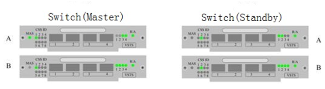
As shown in the following figure, two Huawei S9700s set up a cluster through stack cards. The configurations are correct and switches run stably. When the cluster runs for a long time, the indicators on stack cards are in abnormal state.
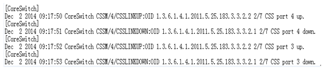
Alarm Information
Log in to a switch. The following Up/Down alarm is generated on the switch:
Handling Process
Collect and save device information with the permission of customer.
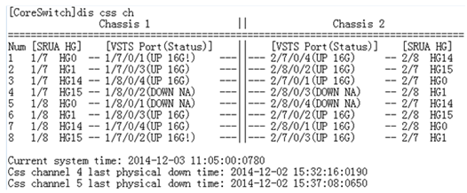
1. Log in to a switch to view cluster information. The information is abnormal:
- Interchange the cables on channels 1 and 2 of active chassis card A with the cables on channels 1 and 2 of active chassis card B. Interchange the cables on channels 3 and 4 of standby chassis card A with the cables on channels 3 and 4 of standby chassis card B. Ensure correct connection sequence.
− If the alarm persists and the indicators on ports 1 and 2 of active chassis card B and on ports 3 and 4 of standby chassis card B are off, the cluster cable is faulty. Replace the cable.
− If the alarm persists and the indicators on ports 1 and 2 of active chassis card A and on ports 3 and 4 of standby chassis card A are off, the cluster card is faulty. Go to the next step.3. Undo all cluster-related commands and power off switches. Interchange cards A and B on active chassis and correctly connect cluster cables. Power on the switches and reconfigure the cluster functions.
− If the alarm persists and the indicators on ports 1 and 2 of active chassis card B and on ports 3 and 4 of standby chassis card B are off, channels 1 and 2 on the original active chassis card A fail. Replace the stack card.
− If the alarm persists and the indicators on ports 1 and 2 of active chassis card A and on ports 3 and 4 of standby chassis card A are off, go to the next step.4. Undo all cluster-related commands and power off switches. Interchange cards A and B on standby chassis and correctly connect cluster cables. Power on the switches and reconfigure the cluster functions. If the alarm persists and the indicators on ports 1 and 2 of active chassis card B and on ports 3 and 4 of standby chassis card B are off, channels 3 and 4 on the original standby chassis card A fail. Replace the stack card.
Root Cause
A stack card has a hardware fault.
Solution
Replace the stack card.
Suggestions
If the log cannot help you locate the fault, minimize the fault scope to locate the failure point.
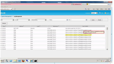
The time of syslog on Network Management is 8 hours later than the local time of device
Issue Description
The time of syslog on Network Management is 8 hours later than the local time of the device
Alarm Information
None
Handling Process
Add the following command to change the syslog time sending to Network Management:
[huawei]info-center loghost x.x.x.x local-time
Root Cause
Although the local time is displayed on the device UTC +8, but the time which the device sends syslog is UTC time. Therefore, the time of syslog displayed on Network Management device is time later than 8 hours
Suggestions
modify the time of syslog to local tme of device.
For more solution of Huawei products, please try:
Contact information:
Telephone: 852-30623083
Email: Sales@Thunder-link.com
Supports@Thunder-link.com
Website: http://www.thunder-link.com
The timestamp of the syslog messages differs from the time synchronized from the NTP server
Issue Description
The S5700 switch synchronizes its time from a NTP server which provides the time in an UTC format. The switch is located in a different region with the NTP server and is configured to add an offset of 2 hours to the UTC time according to the local time zone. Along with the NTP configuration the switch is set to send the log information to a syslog server where the logs are received with a different timestamp than the current time of the device.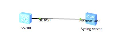
Current time of the switch:
[R6_U24_S5710_Stack]display ntp-service status
clock status: synchronized
clock stratum: 3
reference clock ID: 192.168.64.1
nominal frequency: 60.0002 Hz
actual frequency: 60.0002 Hz
clock precision: 2^17
clock offset: 0.0000 ms
root delay: 17.52 ms
root dispersion: 0.21 ms
peer dispersion: 0.00 ms
reference time: 18:09:50.411 UTC Jan 5 2001(BE008C6E.694A2B9D) //time received from NTP server
synchronization state: clock set
[R6_U24_S5710_Stack]display clock
2001-01-05 21:10:09+03:00 //time adjusted on the switch according to the local timezone
Friday
Time Zone(BUC) : UTC+03:00
Info-center configuration of the device:
[R6_U24_S5710_Stack]info-center loghost 172.1.1.19
Warning: There is security risk as this operation enables a non secure syslog protocol.
The timestamp of the logs received on the syslog server present the time in UTC format:
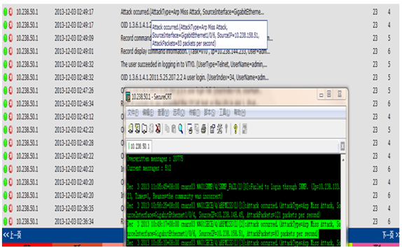
5/23/2016 12:12:31 PM | 192.168.64.9 | Local7 | Info | Jan 5 2001 18:11:06 R6_U24_S5710_Stack %%01MSTP/6/RECEIVE_MSTITC(l)[18]:MSTP received BPDU with TC, MSTP process 0 instance 0, port name is GigabitEthernet0/0/1.
5/23/2016 12:12:42 PM | 192.168.64.9 | Local7 | Notice | Jan 5 2001 18:11:17 R6_U24_S5710_Stack %%01SHELL/5/CMDRECORD(s)[19]:Record command information. (Task=VT0, Ip=172.1.1.19, VpnName=, User=admin, AuthenticationMethod=”Local-user”, Command=”quit”, Result=Success)
Solution
The timestamp of the syslog displays the UTC time by default and in this situation we should adjust the syslog configuration by adding the local-time parameter in the info-center loghost command as below:
[R6_U24_S5710_Stack]info-center loghost 172.1.1.19 local-time
After the local-time parameter is added, the syslog messages should be sent with the current time of the switch.
Result:
5/23/2016 12:12:50 PM | 192.168.64.9 | Local7 | Notice | Jan 5 2001 21:11:25+03:00R6_U24_S5710_Stack %%01SHELL/5/CMDRECORD(s)[20]:Record command information. (Task=VT0, Ip=172.1.1.19, VpnName=, User=admin, AuthenticationMethod=”Local-user”, Command=”info-center loghost 172.1.1.19 local-time”, Result=Success)
5/23/2016 12:12:50 PM | 192.168.64.9 | Local7 | Notice | Jan 5 2001 21:11:25+03:00 R6_U24_S5710_Stack %%01SHELL/5/CMDRECORD(s)[21]:Slot=1;Record command information. (Task=HS2M, Ip=172.1.1.19, VpnName=, User=admin, AuthenticationMethod=”Local-user”, Command=”info-center loghost 172.1.1.19 local-time”, Result=Success)
For more Huawei Switch model, please check http://www.thunder-link.com
There are 30 seconds delay when SSH to S5700 switch
Issue Description
Customer configured SSH service on our Huawei S5700. When he access to our S5700 switch through one SSH client. He found there are 30 seconds delay during the access
Through the debugging information (debugging ssh server all all ), we found the debugging is stuck in below process. There is around 21 seconds delay.
<Test>
Jul 17 2015 22:28:41.60.3+01:00 Test SSH/7/NO_INFO:Begin to compute the dh shared key.
<Test>
Jul 17 2015 22:29:03.790.1+01:00 Test SSH/7/RECV_PKT:Received ssh2 msg ecdh reply packet.
<Test>
Handling Process
1.Analyzed the configuration and confirmed that everything is fine. Trying to set up one test environment to verify it.
2.From the debugging information, I found the SSH client customer used is OpenSSH_6.9
Jul 17 2015 22:28:40.830.1+01:00 CPE-POLIZIA_LOCALE SSH/7/VERSION_RECEIVE:Version information received on VTY 1, version string:SSH-2.0-OpenSSH_6.9.
3.Using Cygwin linux environment to built ssh client. after that, test SSH service and faced same issue with cusotmer. There is big delay when S5700 campute DH shared key.
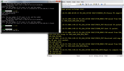
4.Debugging this case with RnD. And we found OpenSSH tool is using long bit key with 2068/4097. Since S5700 is low-end switch, the performance is not very strong and it takes long time to compute the shared key.
debug1: SSH2_MSG_KEX_DH_GEX_REQUEST(1024<8192<8192) sent
debug1: got SSH2_MSG_KEX_DH_GEX_GROUP
debug2: bits set: 2068/4096
debug1: SSH2_MSG_KEX_DH_GEX_INIT sent
5.Based on above analysis, we provide one solution: Change the key algorithm on SSH client.
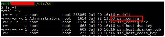
Add below command in file /root/.ssh/config or /etc/ssh/ssh_config
KexAlgorithms=diffie-hellman-group1-sha1
After that, we tested it and there is only 2~3 seconds delay. The problem is solved.
Root Cause
The OpenSSH client uses long bit SSH key and exceed the performance of S5700. S5700 takes long time to compute the DH shared key with SSH client.
Solution
Based on above analysis, we provide one solution: Change the key algorithm on SSH client.
Add below command in file /root/.ssh/config or /etc/ssh/ssh_config
KexAlgorithms=diffie-hellman-group1-sha1
When use the windows as NTP server, equipment not synchronization or continuance shock
Issue Description
When used Windows as NTP server, equipment have problem to synchronization NTP time, not synchronization or continuance shock. Use other equipment as the NTP server, can synchronization time.
Handling Process
Step 1: confirm the NTP server version, is usually have this problem in Windows 2003 or Windows 2008, other versions windows rarely have this problem.
Step 2: open debugging ntp all in the equipment, check the response packet receive from server.
Packet from *.*.*.* (server address) to *.*.*.* (local address) on Vlanif1
Leap: 0, version: 3, mode: 4
Stratum., poll 1: 64, precision: 2 ^6
Rdel: 0.000, rdsp: 10110.870, refid LOCL.
The packet’s rdsp value is 10110.870, which is about 10000ms, can determine the problem is that the rsp value in windows response packet is too large, lead to NTP does not function normally.
Root Cause
Windows 2003 and windows 2008 the two versions, the default NTP rdsp value is 10s, lead to Huawei equipment thinks it’s not normal, affected NTP synchronization.
Other windows versions, the default values are all 0, Huawei equipment can process normally, but have the possibilty of modified to a non-zero value.
Solution
Step 1: In Windows server, enter regedit to into regedit, change as follow:
HKEY_LOCAL_MACHINE \ SYSTEM \ CurrentControlSet \ services W32Time \ Config \ LocalClockDispersion this field, from 10 change it to 0
For more information
Telephone: 852-30623083
Email: Sales@Thunder-link.com
Supports@Thunder-link.com
Website: http://www.thunder-link.com
Which Switch Models Support the PoE Function
Issue Description
Which Switch Models Support the PoE Function?
Solution
Fixed switches
You can use the display device command to check a switch’s product name and determine whether the switch supports the PoE function according to its product name.
- If the product name contains PWR, this switch model supports the PoE function.
- If the product name does not contain PWR, this switch model does not support the PoE function.
Modular switches
Among modular switches, only the S7700 series switches support the PoE function. The PoE card of an S7700 is ES0D0G48VA00.
